High Quality 25g Module - 25GBASE-LR SFP28 1310nm 10km Hi-Optel HSFP28-2321 module – Hi-optel
High Quality 25g Module - 25GBASE-LR SFP28 1310nm 10km Hi-Optel HSFP28-2321 module – Hi-optel Detail:
Descriptions
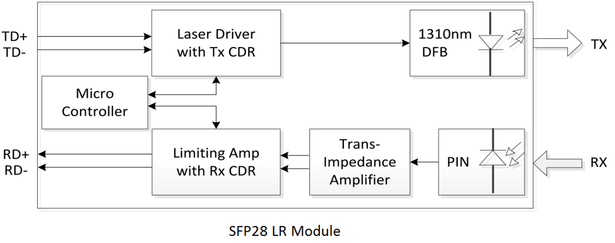
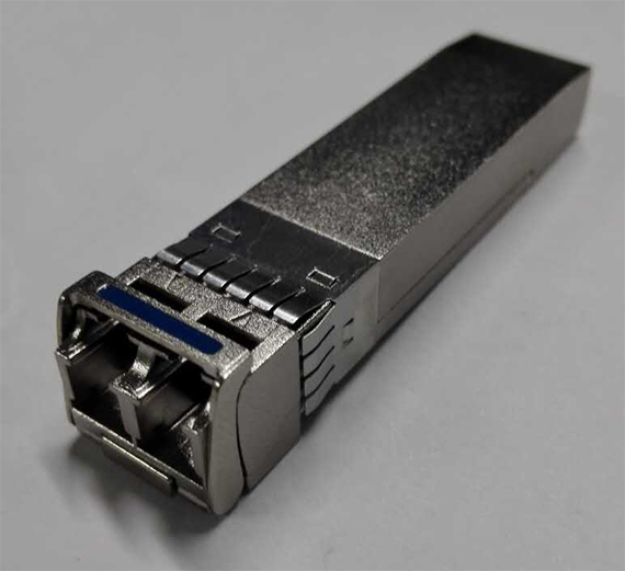
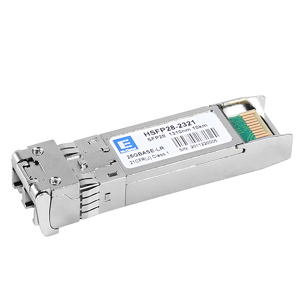
HSFP28-2321 is SFP28 module for duplex optical data communications support 25.78 Gb/s and 28.05 Gb/s data links. It is with the SFP+ 20-pin connector to allow hot plug capability. Digital diagnostic functions are available via an I2C. It has built-in dual clock and data recovery (CDR). This module is designed for single-mode fiber and operates at a nominal wavelength of 1310nm. The transmitter section uses a high performance 1310nm DFB laser and is a class 1 laser compliant according to International Safety Standard IEC-60825. The receiver section uses an integrated InGaAs detector pre-amplifier (IDP) mounted in an optical header and a limiting post-amplifier IC.
Features
● Compliant with MSA SFP+ Specification SFF-8402
● Monitoring Interface Compliant with SFF-8472
● Single +3.3V Power Supply
● Hot-Pluggable
● Built-in dual CDR
● Support 25.78 Gb/s and 28.05Gb/s Data Links
● Up to 10Km on 9/125um SMF
● Very low EMI and excellent ESD protection
● Operating Case Temperature: 0℃~+70℃
● Power Dissipation < 1.2W
● RoHS Compliant Products
Application
● 25GbE
● 32GFC
● Other Optical Links
Pin Description
|
Pin |
Symbol |
Name/Description |
Ref |
| 1 | VeeT | Transmitter Ground(Common with Receiver Ground) | 1 |
| 2 | Tx Fault | Transmitter Fault. Low normal operation, High Fault indication | |
| 3 | Tx Disable | Transmitter Disable. Laser output disabled on high or open | 2 |
| 4 | SDA | Module Definition 2.Data line for Serial ID | 3 |
| 5 | SCL | Module Definition 1.Clock line for Serial ID | 3 |
| 6 | MOD-ABS | Module Definition 0.Grounded within the module | |
| 7 | RS0 | Rate Select 0, optionally controls SFP28 module receiver. LVTTL Logic. | 5 |
| 8 | LOS | Loss of Signal indication. Logic 0 indicates normal operation. | 4 |
| 9 | RS1 | Rate Select 1, optionally controls SFP28 module transmitter. LVTTL Logic. | 5 |
| 10 | VeeR | Receiver Ground(Common with Transmitter Ground) | 1 |
| 11 | VeeR | Receiver Ground(Common with Transmitter Ground) | 1 |
| 12 | RD- | Receiver Inverted DATA out.AC Coupled | |
| 13 | RD+ | Receiver Non-inverted DATA out.AC Coupled | |
| 14 | VeeR | Receiver Ground(Common with Transmitter Ground) | 1 |
| 15 | VccR | Receiver Power Supply | |
| 16 | VccT | Transmitter Power Supply | |
| 17 | VeeT | Transmitter Ground(Common with Receiver Ground) | 1 |
| 18 | TD+ | Transmitter Non-inverted DATA in.AC Coupled | |
| 19 | TD- | Transmitter Inverted DATA in.AC Coupled | |
| 20 | VeeT | Transmitter Ground(Common with Receiver Ground) | 1 |
Notes:
1. Circuit ground is internally isolated from chassis ground. VeeR and VeeT may be internally connected within the SFP28 module.
2. Laser output disabled on TDIS >2.0V or open, enabled on TDIS <0.8V.
3. Should be pulled up with 4.7k – 10kohms on host board to a voltage between 2.0V and 3.6V.
4. LOS is open collector output. Should be pulled up with 4.7k – 10kohms on host board to a voltage between 2.0V and 3.6V. Logic 0 indicates normal operation; logic 1 indicates loss of signal.
5. Pulled low to VeeR or VeeT with a >30K resistor within the SFP28 module.
Product detail pictures:
Related Product Guide:
Our mission will be to become an innovative supplier of high-tech digital and communication devices by furnishing benefit added structure, world-class manufacturing, and service capabilities for High Quality 25g Module - 25GBASE-LR SFP28 1310nm 10km Hi-Optel HSFP28-2321 module – Hi-optel , The product will supply to all over the world, such as: Cannes, Guatemala, Anguilla, Our technical expertise, customer-friendly service, and specialized merchandise make us/company name the first choice of customers and vendors. We've been looking for your inquiry. Let's set up the cooperation right now!
Production management mechanism is completed, quality is guaranteed, high credibility and service let the cooperation is easy, perfect!


